Power plant operators and maintenance teams face ongoing challenges to ensure equipment reliability. Three key failure mechanisms threaten turbine integrity and efficiency.
Allied Power Group, a leading industrial turbine component repair company in Houston, Texas, has pinpointed these threats. Corrosion impacts nearly every engineering structure. Fatigue mainly occurs in components under fluctuating stress. Creep is prevalent under high-temperature conditions in critical parts.
These failure mechanisms often interact, exacerbating damage and speeding up turbine component wear. Grasping the differences between them is vital for effective maintenance planning and replacement strategies.
Accurate identification of each turbine failure mechanism allows for targeted preventive actions. This knowledge aids in extending equipment life and preventing expensive unplanned shutdowns. Distinguishing between these processes is critical for maintaining turbine performance and plant economics.
Key Takeaways
- Three primary failure mechanisms threaten turbine reliability: material degradation from high temperatures, damage from fluctuating stress, and chemical deterioration
- Each mechanism operates through different physical processes requiring distinct diagnostic approaches
- These failure modes frequently interact synergistically, accelerating component damage
- Understanding these differences directly impacts maintenance scheduling and cost management
- Proper identification enables targeted preventive measures and extended equipment lifespan
- Allied Power Group provides expert analysis and repair services for all three failure mechanisms
Understanding Critical Failure Mechanisms in Industrial Turbines
The reliability of turbine engines depends on understanding degradation processes over time. Allied Power Group offers insights into failure mechanisms affecting turbines across U.S. power generation. Three distinct processes threaten operational integrity and turbine performance.
Corrosion, fatigue, and creep are the fundamental mechanisms compromising turbine systems. Each failure mechanism operates through different principles and progresses at varying rates. Understanding enables operators to implement targeted turbine maintenance strategies, extending component life and maintaining reliable turbine power output.
The Three Primary Failure Modes Affecting Turbine Performance
Corrosion occurs in structures exposed to reactive environments. This chemical degradation attacks surfaces exposed to moisture, combustion byproducts, or contaminants, weakening turbine blade integrity and accelerating other failure mechanisms.
Fatigue occurs in parts experiencing rapid vibratory, rotational, or reciprocatory motion. This failure mode results from cyclic loading initiating microscopic cracks at stress points. Moving blades and rotating blades face constant stress fluctuations. Avoiding fatigue failure depends on good surface finish and proper design of turbine components.
Creep involves time-dependent deformation under sustained stress at elevated temperatures. Creep is of great importance in high-pressure steam or gas turbine operations. This progressive deformation accumulates over thousands of hours in hot section components of gas turbine engine installations.
Material selection determines which failure mode dominates. Advanced turbine designs incorporate alloy materials engineered to resist degradation mechanisms. Blade made of nickel-based superalloy materials provide exceptional resistance. Real-world turbine operations involve complex interactions—corrosion creates defects where fatigue cracks can initiate, while creep changes stress distributions accelerating fatigue damage.
Impact on Gas Turbine and Steam Turbine Operations
Gas turbine systems face unique challenges due to extremely high combustion temperatures and rapid thermal cycling. Hot section components in a gas turbine engine experience temperatures exceeding 2,300°F, making creep the dominant concern for turbine blade integrity. Startup and shutdown cycles introduce thermal fatigue as components expand and contract.
The design of turbine hot gas paths must account for extreme conditions through material selection and cooling strategies. Nickel-based superalloys provide exceptional creep resistance at elevated temperatures. Thermal barrier coatings add protection in the section of a gas turbine experiencing maximum thermal stress.
Steam turbine installations operate at lower peak temperatures but face different challenges. Low-pressure sections encounter moisture promoting corrosion on steam turbine blades surfaces. High-pressure stages experience temperatures where creep becomes relevant. Location within turbine systems determines which degradation mechanism poses the greatest threat—first-stage turbine blade components experience maximum temperatures and centrifugal stresses.
| Failure Mode | Primary Cause | Most Affected Components | Key Prevention Strategy |
|---|---|---|---|
| Creep | High temperature and sustained stress | Hot section blades and rotors | Temperature management and alloy selection |
| Fatigue | Cyclic mechanical or thermal loading | Rotating components and attachments | Surface finish control and stress reduction |
| Corrosion | Chemical reaction with environment | Exposed surfaces in moisture zones | Protective coatings and material resistance |
Turbine Creep: Progressive Deformation Under High Temperature and Stress
Turbine components face unique challenges operating under sustained stress and elevated temperatures. This is creep. Unlike sudden failures, creep is gradual—metals slowly change shape over time. This poses risks in power generation where components must maintain precise dimensions. Creep occurs when materials experience prolonged stress at high temperature, activating atomic-level processes allowing metal crystals to deform slowly.
Physical Mechanisms Behind Blade and Rotor Deformation
Creep mechanisms operate at the atomic level in structures exposed to hot gas paths or pressure steam environments. When temperatures exceed roughly half the melting point of an alloy, thermal energy allows atoms to move freely. This enables deformation processes that don’t occur at lower temperatures.
Dislocation climb represents one mechanism where crystal structure defects move under stress. Grain boundary sliding occurs when crystals shift relative to neighbors. The creep rate depends on temperature, stress levels, and material composition.
Engineers classify creep into three stages. Primary creep shows decreasing strain rate as material work-hardens. Secondary creep maintains steady, constant rate. Tertiary creep exhibits accelerating creep strain leading to rupture. Gas turbine blade assemblies face severe creep conditions—the hot section exposes airfoils to combustion temperatures exceeding 1,200°C while centrifugal forces create tremendous tensile stress. The turbine rotor experiences different but challenging conditions, with forgings operating under high-pressure steam while supporting massive centrifugal loads.
| Creep Stage | Deformation Behavior | Duration Characteristics | Inspection Indicators |
|---|---|---|---|
| Primary Creep | Decreasing strain rate with work hardening | Initial operating period, hours to months | Minor dimensional changes, no visible distortion |
| Secondary Creep | Constant steady-state deformation rate | Majority of component life, months to years | Gradual elongation, measurable dimension change |
| Tertiary Creep | Accelerating strain with microcrack formation | Final phase before failure, weeks to months | Visible distortion, surface cracking, rapid changes |
Advanced Materials Engineering for Temperature Resistance
Modern blade made of nickel-based superalloy materials represent decades of development maximizing creep resistance. These specialized compositions maintain structural integrity at temperatures where conventional steels would quickly deform. A blade made of nickel-based superalloy operates reliably in conditions destroying lesser materials within hours.
Superior high temperature performance lies in complex alloying strategies. Nickel provides the base with good elevated temperature properties. Chromium enhances oxidation resistance while contributing to strengthening. Aluminum and titanium form precipitates that pin dislocations and inhibit atomic movements enabling creep.
Precipitation strengthening creates microscopic particles distributed throughout alloy structure. These precipitates remain stable at high temperature and block dislocation movement. Manufacturing techniques enhance creep resistance beyond chemistry alone. Single-crystal casting eliminates grain boundaries entirely within individual turbine blade components, demonstrating dramatically improved resistance. Material selection must balance creep resistance with thermal fatigue resistance, high-temperature corrosion resistance, and ductility.
Detection Methods for Maintenance Decision-Making
Identifying significant creep damage during turbine maintenance requires specialized techniques. Unlike sudden fracture, creep produces gradual changes not immediately obvious during visual examination. Dimensional measurements provide direct evidence—inspectors measure blade lengths checking for elongation. Airfoil profiles are mapped to detect twisting. These measurements reveal whether measurable creep has occurred in turbine blade assemblies.
Metallurgical evaluation examines microstructure for creep damage signs. Allied Power Group’s Houston facility has extensive experience evaluating creep damage and recommending replacement strategies for components showing creep deformation. The cumulative nature of creep makes early detection critical—once material has deformed, it cannot be restored. Components with excessive creep must be replaced. Understanding the relationship between creep and fatigue helps inspectors recognize when combined mechanisms accelerate degradation.
Creep, Fatigue, and Corrosion: Distinguishing Each Turbine Failure Mechanism
Understanding creep, fatigue, and corrosion is key to protecting turbine materials. Each mechanism attacks materials in unique ways, compromising component integrity. Accurate diagnosis and prevention strategies depend on these distinctions.
Creep causes plastic deformation under sustained stress at high temperatures. Fatigue results from cyclic loading that initiates and propagates cracks. Corrosion involves chemical or electrochemical degradation of material surfaces.
The table below summarizes the key distinguishing characteristics of each failure mechanism:
| Failure Mechanism | Primary Cause | Operating Conditions | Visual Evidence |
|---|---|---|---|
| Creep | Sustained stress at elevated temperature | Continuous high-temperature operation above 50% melting point | Elongation, necking, void formation, grain boundary separation |
| Fatigue | Cyclic or fluctuating stress | Repeated loading cycles from vibration, thermal cycling, or startups | Crack initiation sites, propagation marks, beach marks, final rupture zone |
| Corrosion | Chemical or electrochemical attack | Exposure to aggressive environment with moisture, contaminants, or reactive gases | Surface pitting, oxide layers, material loss, corrosion products, discoloration |
Fatigue Failure in Rotating and Moving Blades
Fatigue failure occurs when components experience cyclic or fluctuating stress initiating and propagating cracks. Unlike creep developing under sustained loading, fatigue damage accumulates through repeated stress cycles. Even when stress remains below material strength, millions of cycles lead to catastrophic failure.
The rotating blades and moving blades in turbines face constant cyclic loading. Vibrations from aerodynamic forces create stress fluctuations in gas turbine blade and steam turbine blades assemblies. These alternating stresses concentrate at geometric discontinuities.
Engineers distinguish between two fatigue categories. Due to high cycle fatigue, rotor blades develop damage from low-amplitude stress cycles repeated millions of times. Low cycle fatigue failure results from fewer cycles with higher stress amplitudes during startup and shutdown creating thermal gradients in compressor blade components.
Fatigue cracks can initiate where stress concentrations occur. The blade root attachment represents a common initiation site due to high stresses. The edge of the blade experiences high centrifugal loads and aerodynamic forces. Blades after foreign object damage become vulnerable to crack formation.
Different turbine sections experience distinct fatigue patterns. Blades in a gas turbine hot section face combined mechanical and thermal fatigue. The low pressure turbine and low pressure steam turbine blade components operate at lower temperatures but encounter different stress patterns. Temperature fluctuations during startup create thermal stress damaging sections experiencing severe gradients. Fatigue crack propagation follows predictable patterns investigators use during failure analysis. Understanding how blades operate helps predict where fatigue damage develops, extending fatigue life.
Corrosion and Oxidation Damage in Turbine Environments
Corrosion damage involves chemical reactions degrading turbine materials. Unlike mechanical processes of creep and fatigue, corrosion attacks material composition directly. Multiple forms threaten turbine components depending on environment and material selection.
High-temperature corrosion affects components in the hot gas path. Reactive gases attack protective oxide layers on surfaces. This high temperature corrosion accelerates when contaminants deposit on hot surfaces. Localized corrosion creates concentrated attack forming pits acting as stress concentrations significantly reducing fatigue life.
Steam turbine environments present different corrosion challenges. Moisture in low-pressure stages enables electrochemical reactions causing corrosion and oxidation. The blade steel in different environments exhibits varying corrosion resistance depending on alloy composition and protective coatings.
Stress corrosion cracking represents a dangerous form requiring tensile stress, susceptible material, and corrosive environment. Cracks propagate without significant metal loss, making detection difficult. Corrosion products accumulate on surfaces as oxidation progresses. Thermal cycling causes protective films to crack and spall, exposing fresh metal.
The interaction between corrosion and fatigue creates severe degradation. Corrosion fatigue occurs when cyclic loading combines with environmental attack. This synergistic effect reduces component life below what either mechanism causes independently. Several mechanisms explain how fatigue and corrosion accelerate damage. Corrosion pits create stress concentrations becoming preferential sites where fatigue cracks can initiate. Blade steel in different environments requires appropriate material selection for corrosion resistance.
Corrosion and erosion often work together in the gas path where particulates impact surfaces. Erosion removes protective oxide layers while corrosion attacks exposed material. This combined mechanism causes rapid degradation in compressor sections. Understanding how environments affect materials guides turbine maintenance strategies for oil and gas production plant applications.
Root Cause Analysis and Failure Investigation Methods
Root cause analysis provides systematic methods determining why failure of the turbine blade occurred. Allied Power Group employs advanced diagnostic methods at their Houston facility. These techniques distinguish between different failure mechanisms and identify underlying causes affecting turbine efficiency.
Investigation of turbine blade failure begins with thorough documentation of operating history. Visual examination provides initial clues about failure mode. The failure analysis team photographs failed components before cleaning. Fracture surface characteristics indicate whether failure of the blade resulted from creep, fatigue, corrosion, or combined mechanisms.
Distinguishing one failure mechanism requires understanding characteristic features. Creep damage shows plastic deformation with elongation before rupture. Cavities form along grain boundaries as creep progresses. Fatigue crack surfaces exhibit distinct markings revealing progressive crack growth. Corrosion damage displays chemical attack evidence including pitting, oxide layers, and corrosion products. Analysis of gas turbine components requires specialized knowledge of operating conditions.
Failure in a thermal power plant involves additional considerations related to steam quality. The failure of steam turbine components often results from combined mechanisms where corrosion fatigue plays significant roles. Examination of blade failure in a thermal environment requires assessing whether temperature exceeded material capabilities.
Metallurgical evaluation provides definitive evidence about failure mechanisms. Microscopic examination reveals microstructure changes. Examination of blades and discs interfaces reveals loading conditions during failure. Chemical analysis identifies whether contaminants contributed. Understanding how blades were made and their original properties provides baseline comparison.
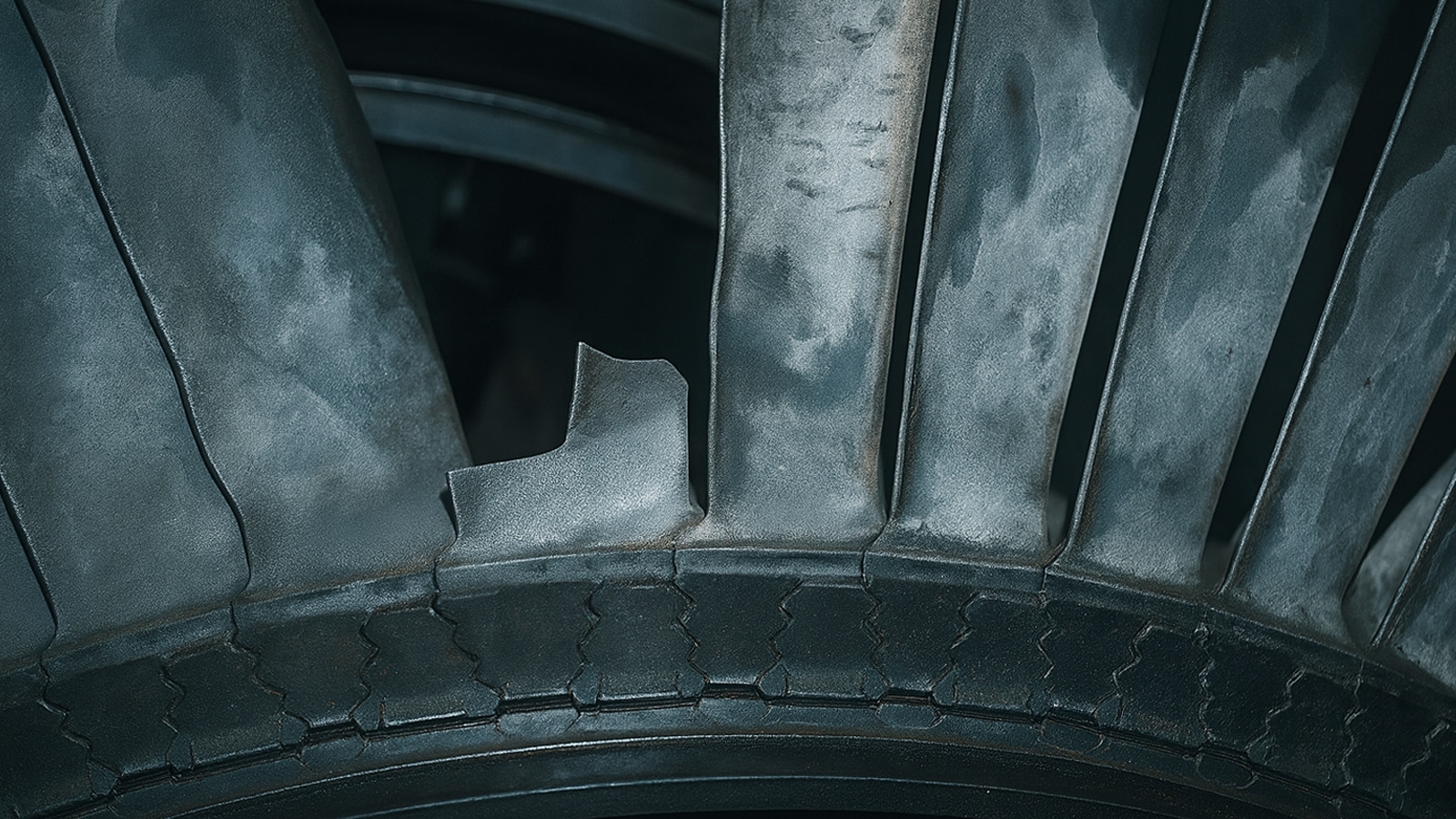
Broken blades represent serious failures affecting turbine support structures. When failure of the blade occurs, fragments travel through the gas path at high velocity, causing secondary damage. Allied Power Group’s failure investigation expertise extends across multiple turbine types. Accurate root cause analysis enables effective corrective actions. Material upgrades improve resistance to identified failure mechanisms.
Conclusion: Protecting Your Turbine Investment Through Expert Analysis
Understanding creep, fatigue, and corrosion is key for effective turbine maintenance. Creep is deformation under high temperatures over time. Fatigue comes from repeated loading cycles. Corrosion is chemical damage to turbine parts. Each needs its own diagnostic and repair methods.
In real-world operations, turbines often face multiple failure modes. Accurate diagnosis is critical. Misdiagnosis can lead to wrong repairs and early replacements, increasing costs.
Allied Power Group, based in Houston, Texas, offers top-notch turbine repair and failure analysis. Their team knows how operating conditions, material properties, and failure mechanisms interact. This helps facilities keep equipment reliable and downtime low. Identifying damage sources impacts repair choices and replacement timing. Expert analysis ensures fixes tackle real problems. Allied Power Group has the know-how to extend component life and boost turbine power generation, ensuring turbines run reliably.
FAQ
What are the three primary failure mechanisms affecting industrial turbines?
Industrial turbines face three main failure mechanisms: creep, fatigue, and corrosion. Creep is time-dependent deformation under sustained stress at elevated temperatures, prevalent in hot section components. Fatigue occurs from cyclic loading initiating and propagating cracks in moving blades and rotating blades. Corrosion involves chemical degradation of turbine blade surfaces. These mechanisms often interact synergistically, with corrosion creating defects where fatigue cracks can initiate, or creep deformation changing stress distributions accelerating fatigue damage.
How does creep damage occur in gas turbine and steam turbine components?
Creep damage occurs when turbine components experience elevated temperatures enabling atomic-level mechanisms like dislocation climb and grain boundary sliding, allowing materials to deform progressively under constant stress. In gas turbine blade assemblies, centrifugal forces combined with combustion temperatures exceeding 2,300°F create ideal conditions for significant creep. The process progresses through three stages: primary creep with decreasing strain rate, secondary steady-state creep with constant creep rate, and tertiary creep with accelerating creep strain leading to rupture. Measurable creep manifests as dimensional changes including blade elongation and twisting, requiring component replacement since creep deformation is irreversible.
Why are nickel-based superalloy materials used in advanced turbine hot sections?
Modern blade made of nickel-based superalloy materials provide superior creep resistance at extreme temperatures through advanced metallurgy. These alloys incorporate precipitation strengthening mechanisms creating microscopic particles inhibiting atomic movements enabling creep. Single-crystal casting techniques eliminate grain boundaries, dramatically improving creep resistance. The alloy must balance multiple properties: creep resistance at high temperature, thermal fatigue resistance during temperature cycling, high-temperature corrosion resistance from combustion products, and adequate fatigue life. This makes nickel-based superalloy materials ideal for gas turbine hot section applications where creep would cause rapid degradation.
How do corrosion and fatigue cracking interact to reduce turbine component life?
Corrosion fatigue represents synergistic effects where fatigue and corrosion combine reducing component life below what either mechanism causes independently. Corrosion creates pits acting as stress concentrations that accelerate where fatigue cracks can initiate. Corrosive environments eliminate the fatigue limit observed in benign conditions, meaning materials enduring infinite cycles in clean air fail after finite cycles when exposed to aggressive chemistry. This interaction is significant in steam turbine blades where moisture-induced corrosion in low pressure turbine sections combines with cyclic loading. The edge of the blade and blade root attachment areas are particularly vulnerable to combined corrosion damage and fatigue crack propagation.
Why is root cause analysis essential for addressing turbine blade failure events?
Root cause analysis is essential because accurate identification of whether component damage results from creep, fatigue, corrosion, or combined mechanisms directly impacts repair decisions, component replacement timing, and preventive turbine maintenance strategies. Misdiagnosing failure mechanisms leads to inappropriate repairs and inadequate corrective actions allowing failure recurrence. Allied Power Group’s systematic approach to investigation of turbine blade failure includes documenting operating conditions, turbine maintenance history, visual examination, dimensional measurements, and metallurgical evaluation determining whether failure is due to material defects, operational overstress, or environmental attack. This thorough failure analysis enables targeted corrective actions addressing actual failure mechanisms, protecting turbine power generation assets from unexpected failures and maintaining turbine efficiency.

