

Your Power Partner
7FA Bucket Cracking Explained
The finding is on the report, the borescope images are attached, and the question isn’t academic: can the unit keep running until the next planned outage, or does this need attention now? 7FA bucket cracking most often traces back to thermal mechanical fatigue, high cycle fatigue, creep rupture, oxidation, or DLN combustion dynamics acting on the airfoil over thousands of operating hours, and getting the severity call right doesn’t require guesswork. This article covers the causes, detection methods, and severity thresholds that determine whether a finding is a monitor-and-plan item or a forced-outage risk, and how GE Frame 7F turbine repair teams evaluate repair versus replacement before your next planned outage window closes.
Key Takeaways
- 7FA bucket cracking is typically driven by thermal mechanical fatigue, high cycle fatigue, or creep rupture, each with different repair implications for Stage 1 through Stage 3 hardware.
- Borescope inspection catches surface-visible cracks during a combustion inspection; fluorescent penetrant inspection and CT or white light scanning during a hot gas path inspection catch what borescope misses.
- Not every crack finding is critical. Severity depends on crack length, location, orientation, and hours accumulated since the last inspection.
- Weld repair, blend repair, and thermal barrier coating restoration can often return a bucket to 80-95% of new-part life at a fraction of OEM replacement cost and lead time, making repair the practical, cost-effective option in most severity tiers.
- A second opinion from an engineer before the outage window closes prevents both over-replacing hardware and under-repairing a real risk.
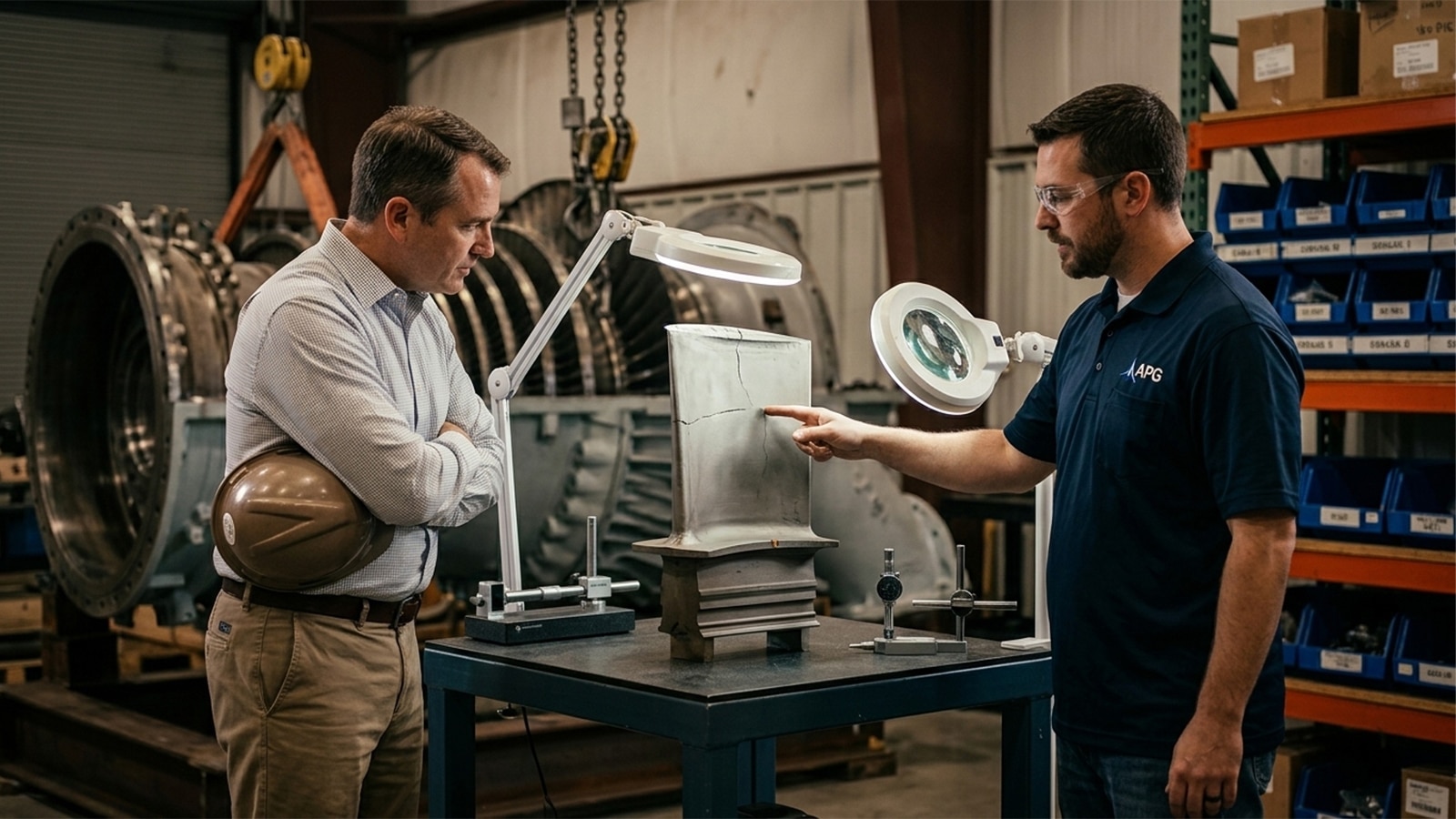
What Is Bucket Cracking and Why It Matters
The GE 7FA gas turbine is one of the most widely operated F-class platforms in North America. That prevalence means bucket cracking findings show up constantly across combustion and hot gas path inspection reports fleet-wide, and gas turbine components across the hot gas path bear the cumulative effects of these findings over time. If this is the first cracking finding you’ve had to size up, you’re not behind the curve. It’s a common report to land on a maintenance director’s desk.
Buckets vs. Blades: Clearing Up the Terminology
GE calls its rotating hot gas path airfoils buckets. The broader industry, and most engineering literature, calls the same components turbine blades. Stationary airfoils that direct flow onto the buckets are nozzles. Three terms, same hardware, same fatigue mechanisms.
Where Stage 1-3 Buckets Sit in the 7FA Hot Gas Path
Stage 1 buckets sit immediately downstream of the combustion system and see the highest gas path temperatures in the machine. That makes them the most cracking-prone of the three stage buckets. Stage 2 and Stage 3 buckets operate at progressively lower temperatures but carry their own mechanical loading profiles, and shroud and blade tip geometry differ between stages.
The Real Risk: Liberation and Downstream FOD
A missed crack is not a paperwork problem. If a crack propagates far enough, a bucket fragment can liberate from the rotor. That fragment travels downstream into later stages, nozzles, and shrouds, sometimes damaging a downstream nozzle badly enough to require its own weld repair. The result is foreign object damage that turns a planned hot gas path inspection into an unplanned rotor event. That’s exactly the outcome every severity framework in this article is built to prevent.
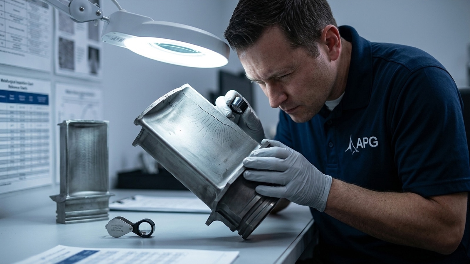
Root Causes of 7FA Bucket Cracking
The root cause of turbine bucket cracking is cyclic thermal and mechanical stress acting on the airfoil alloy, accelerated by coating degradation, oxidation, and combustion dynamics over the bucket’s operating life.
Thermal Mechanical Fatigue and High Cycle Fatigue
Thermal mechanical fatigue (TMF) results from repeated heating and cooling cycles, tied directly to starts, load swings, and fast-start operation. High cycle fatigue (HCF) is driven by vibratory stress, often linked to DLN combustion dynamics and pressure pulsation that excite the airfoil at resonant frequencies. The same pulsation can fatigue an adjacent nozzle over time. Cycling units tend to accumulate TMF damage faster. Baseload units under sustained load build up a different stress pattern entirely.
Creep Rupture and DS Alloy Behavior
Creep rupture is a sustained high-temperature, high-stress mechanism rather than a cyclic one. Directionally solidified (DS) alloy is used in 7FA buckets specifically to resist grain-boundary creep along the airfoil’s primary stress axis. Even so, creep cracking still initiates at grain boundaries in the parent material once hours and temperature exposure run past design assumptions.
Coating Degradation, Oxidation, and Fuel Quality
Bond coat and thermal barrier coating degradation expose the base alloy to oxidation. Tip cap oxidation is a commonly observed finding on 1st stage bucket and 7FA.04 1st blade hardware specifically. Once the airfoil TBC coating is compromised, oxidation works through the bond coat toward the parent material. Erosion from particulate ingestion and fuel quality issues, including contaminants and inconsistent gas composition, add hot corrosion that weakens gas turbine components further over time. A sound repair program is what keeps that degradation from turning into a forced outage.
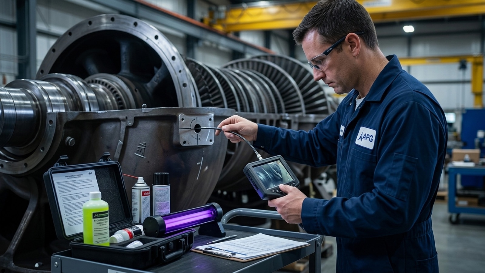
How Cracking Is Detected
Inspecting 7FA buckets for cracks starts with borescope inspection during routine combustion inspections, then escalates to fluorescent penetrant inspection and CT or white light scanning during a hot gas path inspection for anything borescope cannot confirm.
Borescope Inspection During Combustion Inspections
A combustion inspection interval, typically staged around 8,000 equivalent firing hours depending on duty cycle, gives crews borescope access to buckets alongside transition pieces, flow sleeves, and other combustion components. Borescope inspection is fast and non-invasive. But it’s a visual method only, and visual inspection alone will miss subsurface creep damage or wall thinning that hasn’t yet broken the surface.
FPI, CT, and White Light Scanning During HGP Inspections
A hot gas path inspection, generally scheduled around 24,000 equivalent firing hours, allows removal of buckets for fluorescent penetrant inspection. Penetrant inspection reveals surface-breaking cracks far more reliably than a borescope pass. CT scanning and white light scanning add dimensional and subsurface data, catching wall thinning and geometry deviation that neither borescope nor FPI alone will pick up. GE Technical Information Letters (TILs) periodically update inspection interval guidance based on fleet-wide failure trends, and EPRI’s life management research gets used alongside OEM guidance to tune inspection cadence to actual duty cycle.
Where Cracks Most Commonly Appear
- Leading edge, where thermal gradient stress concentrates
- Platform, particularly on Stage 1 buckets under sustained thermal load
- Dovetail, where mechanical stress concentrates at the rotor attachment
- Tip shroud, where tip cracks are among the most commonly observed findings
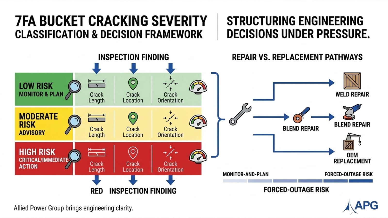
Severity Classification and Repair vs. Replacement Decision Framework
Whether a cracked bucket can be repaired or must be replaced depends on crack length, location, orientation, and alloy condition relative to OEM-defined tolerances. Not on visual impression alone. If your report doesn’t clearly answer which bucket of these you’re in, that’s worth a second look before you plan around it.
Severity Classification: Monitor vs. Critical
| Severity Level | Typical Findings | Recommended Action |
|---|---|---|
| Minor / Monitor | Minimal loss of blade tip height, low erosion and oxidation, shallow leading-edge indications | Log finding, monitor at next combustion inspection interval |
| Moderate | Tip cap oxidation, moderate wall thinning, isolated platform cracking | Plan blend repair or bucket tip restoration at next outage |
| Critical / Immediate Action | Crack length exceeding OEM tolerance, dovetail or shroud cracking, orientation toward liberation risk | Forced outage evaluation, weld or braze repair, or replacement before return to service |
Repair Techniques by Crack Type and Alloy
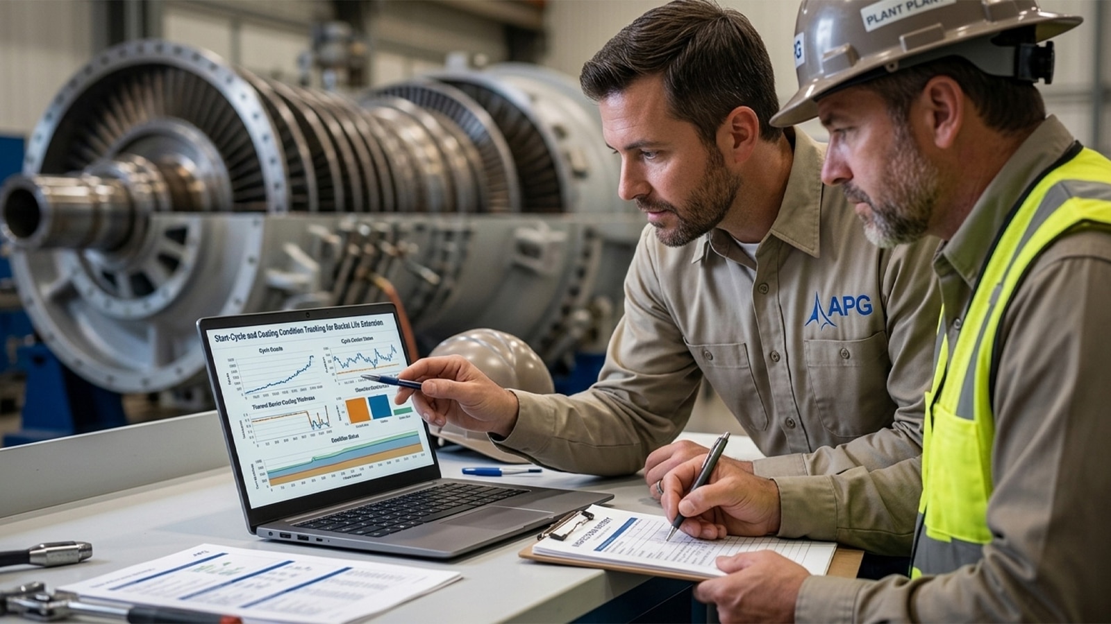
Weld repair and braze repair address parent-material cracks within OEM-defined limits. Blend repair addresses shallow edge damage that doesn’t warrant a full weld cycle. The repair process typically starts with a dimensional and NDE assessment to confirm the finding falls within repairable tolerance before any weld or blend work begins. Bucket tip restoration and dimensional restoration correct tip cap oxidation and geometry loss on stage buckets that are otherwise structurally sound. Repaired blade tips that show low erosion and oxidation are strong candidates for continued service, and TBC reapplication after repair restores the protective barrier the original coating provided, guarding against oxidation of the repaired blade once the part returns to service. These repairs also exhibit excellent abrasion resistance once returned to service, holding up against the particulate exposure and mechanical wear that gas turbine components encounter over subsequent operating cycles.
When Replacement Is the Only Option
Replacement becomes mandatory when cracks exceed blend or weld repair limits, when incoming condition is too degraded to restore dimensionally, or when repeated cracking at the same location signals a design-level fatigue issue rather than a one-off finding. Repair is generally the lower-cost, faster path compared to sourcing new 7FA.04 components through OEM channels, and it remains a highly effective way of extending hardware life while reducing operating costs. That matters directly for IPPs planning around a fixed outage window rather than an open-ended one.
Preventing Future Cracking
Operational Practices That Reduce Cyclic Stress
Fast starts and frequent load swings accelerate TMF accumulation faster than steady baseload operation. Where dispatch flexibility allows it, reducing unnecessary fast-start cycles and moderating ramp rates extends the interval between cracking findings. This is a dispatch and operations conversation as much as a maintenance one, and it’s worth having alongside your inspection planning rather than after the next finding shows up.
Coating Refurbishment and Upgraded Designs
Refurbishing TBC and bond coat on schedule, rather than waiting for oxidation to reach the parent material, is one of the more cost-effective levers available between major inspections. Upgraded bucket designs and coating systems introduced through OEM TILs sometimes offer meaningfully better cracking resistance than original hardware, worth evaluating at your next replacement decision point rather than defaulting to like-for-like.
Monitoring Programs That Catch Trends Early
Tracking crack findings across inspection cycles, rather than treating each report in isolation, reveals whether a given bucket population is trending toward a design-level issue or holding steady within normal wear. That trend data is what turns your next borescope pass from a snapshot into a genuinely predictive tool.
Why IPP Plant Managers Choose Allied Power Group for 7FA Bucket Repair
Repair Capabilities Across the Hot Gas Path
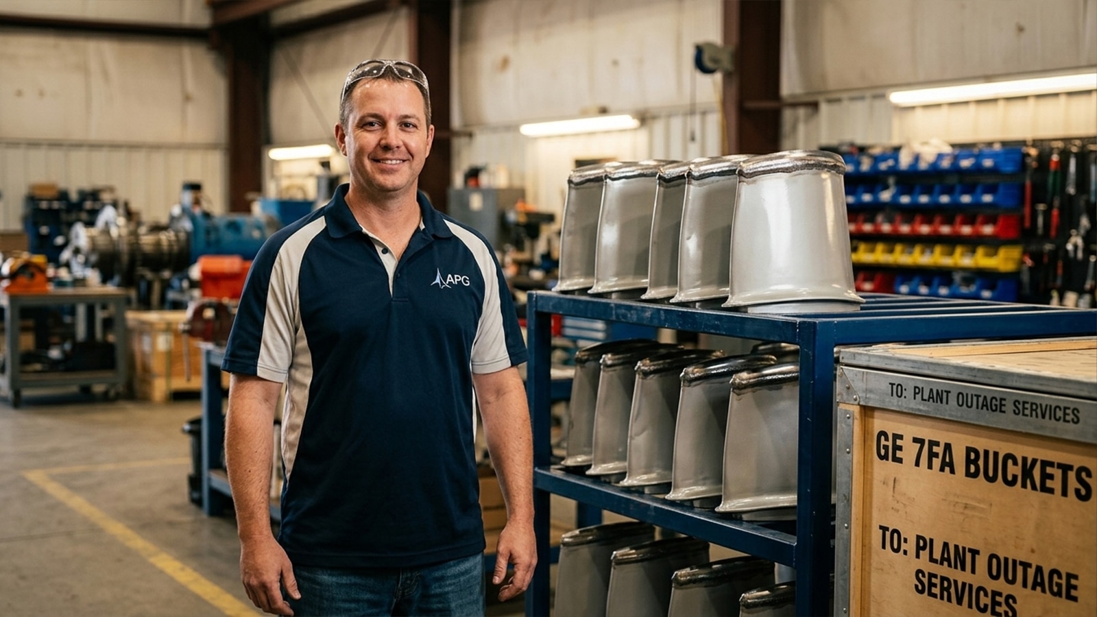
We repair hot gas path components, buckets, nozzles, and combustion hardware, rather than isolated bucket-only work that leaves adjacent findings unaddressed. Our capability spans buckets, nozzles, shrouds, and transition pieces, including weld repair, blend repair, and TBC restoration performed under one engineering-reviewed program rather than farmed out piecemeal. We offer comprehensive repairs across the full gas turbine component repair scope rather than single-part fixes, and our blade repair procedures have proven reliable in returning parts to service. Our repairs also exhibit excellent abrasion resistance under continued thermal and mechanical loading in the field, delivering a cost-effective alternative to OEM replacement without giving up performance.
Cross-Platform Experience: 7FA and 9FA Fleet Support
Our repair work extends across GE fleet platforms, including 9FA gas turbines. That gives our engineering team cross-platform depth that feeds directly back into 7FA-specific repair procedures. AGP gas turbine component repairs are developed and validated against OEM tolerances and documented repair histories, which is what makes a repaired part suitable for continued service rather than a stopgap. The result: extended bucket lifecycle and lower operating costs compared to a default-to-replacement strategy on every finding, giving plant managers a comprehensive repairs pathway that reduces reliance on costly OEM lead times.
If you’re staring at a borescope image right now and trying to decide which row of the severity table it belongs in, that’s a reasonable thing to ask someone else to weigh in on. It’s the kind of question our engineers field regularly, and a quick conversation often clarifies more than another read-through of the report will.
Conclusion: Get an Engineering-Backed Read on Your Bucket Cracking Finding
You now have the vocabulary to read your own inspection report: whether the mechanism is TMF, HCF, or creep, and where a given finding likely falls on the severity table above. That’s real ground to stand on. But the gap between a monitor-and-plan finding and a forced-outage risk is measured in fractions of an inch and degrees of orientation, and misjudging it in either direction costs real money, either in an unplanned trip or in hardware replaced too soon. Getting a second, engineering-backed read before you commit budget or outage scope to a decision isn’t a sign you missed something. It’s the responsible next step.
If it would help to talk through a specific finding, Allied Power Group is reachable at (281) 444-3535. No pressure to have every detail sorted first.
FAQ
What is the root cause of turbine bucket cracking?
Turbine bucket cracking results from thermal mechanical fatigue, high cycle fatigue, creep rupture, and oxidation acting together on the airfoil over its operating life. Coating degradation speeds up each of these mechanisms by exposing the base alloy earlier than the design intended. Identifying which mechanism dominates changes the repair approach entirely, which is why root-cause identification belongs with an engineer who can tell them apart, not a visual judgment call.
How do you inspect 7FA buckets for cracks?
7FA buckets are inspected using a layered approach: borescope inspection during combustion inspections, followed by fluorescent penetrant inspection and CT or white light scanning during a hot gas path inspection. Method selection depends on the suspected crack type and location. An experienced inspection team catches subsurface and dimensional issues that a routine borescope pass alone will miss.
Can cracked turbine buckets be repaired or must they be replaced?
Many cracked buckets are repairable within OEM tolerance limits using weld, braze, or blend repair techniques. Others need replacement once crack length or wall thinning exceeds those limits. The deciding factor is an accurate incoming condition assessment, not visual severity alone.
What is the difference between thermal mechanical fatigue and creep cracking in buckets?
Thermal mechanical fatigue is driven by cyclic thermal and mechanical stress from starts and load changes, common in units that cycle frequently. Creep rupture is driven by sustained high temperature and stress over long operating hours, common in baseload units. Misdiagnosing one for the other leads to the wrong repair strategy, which is why this call should go to a qualified repair engineer.
How often should 7FA Stage 1 buckets be inspected for cracking?
Stage 1 buckets should be inspected at each combustion inspection interval, generally around 8,000 equivalent firing hours, with a full hot gas path inspection around 24,000 equivalent firing hours per GE TIL and OEM guidance. Actual hours and starts both factor into interval decisions. A repair partner can help work out whether standard interval guidance actually fits your unit’s duty cycle.
What is the typical life expectancy of a GE 7FA bucket before cracking occurs?
A GE 7FA bucket’s design life is typically framed in tens of thousands of equivalent operating hours and hundreds of starts, but actual life varies with duty cycle, fuel quality, and coating condition. Cycling units and baseload units wear differently even against the same design-life number. Inspection-based verification is more reliable than leaning on generic design-life figures alone.
How do you decide repair vs. replace on a bucket cracking finding before the next outage?
The decision comes down to severity classification, alloy condition, crack location, and the cost and lead-time tradeoff between repair and new OEM hardware. Repair is frequently the faster, lower-cost path when the finding falls within established tolerance. This decision should be checked against an experienced repair engineering team before locking in outage scope.