

Your Power Partner
GE 7FA.04 vs Earlier 7FA Models: What Changed and Why It Matters (Complete Guide)
If you operate a GE Frame 7FA gas turbine fleet and need to know whether your maintenance plan, spare parts inventory, or upgrade pathway matches your unit’s actual build standard, the sub-variant designation is where that answer starts. The 7FA.04 introduced upgraded compressor aerofoils, revised hot gas path components with enhanced Thermal Barrier Coatings (TBC), an improved DLN 2.6 combustion system, and Mark VIe control upgrades — delivering higher output and improved efficiency compared to 7FA.01 through 7FA.03 builds. For operators evaluating component repair services across mixed fleets, knowing precisely which variant you are running is a prerequisite, not a preference.
Key Takeaways
- The 7FA.03 and 7FA.04 share the same rotor — differences are confined to combustion and hot gas path components
- The 7FA.01 and 7FA.02 have significant design differences from the .03 and .04; parts interchangeability across that generational line is limited
- Many 7FA units installed during the late-1990s and early-2000s buildout are reaching important rotor-life-management thresholds, including 144,000 factored fired hours or 5,000 factored fired starts.
- In a 2014 7F Users Group audience survey, respondents reported that third parties repaired 34% of repaired parts.
What Upgrades Did GE Introduce with the 7FA.04 Variant?
GE Vernova (formerly GE Power) released the 7FA.01 in the early 1990s, with the .02 and .03 following incrementally through the decade. The .04 arrived in the mid-2000s as the most extensively revised build, addressing the compressor, hot gas path, combustion system, and controls simultaneously. That breadth of change is why parts interchangeability across the variant boundary is more limited than operators sometimes assume.
The installed base of F-class gas turbines includes well over 400 units in North America alone. GE production surged from roughly 80 machines per year in 1998 to 240 in 2000, with the majority of those units being 7FA.03 builds. A plant that came online in 1998 is not running the same hardware as one that entered service in 2007 — even if both units carry the same nameplate.
Compressor Aerofoil and Stage Geometry
The 7FA.04 compressor introduced redesigned aerofoil profiles across multiple stages, with a pressure ratio in the range of 15.4:1 compared to approximately 14.7:1 on the .01 build. Revised blade geometry improves aerodynamic efficiency and reduces susceptibility to compressor fouling that operators of earlier builds had documented over extended service intervals. The .04 aerofoil profiles are not interchangeable with .03 hardware in most stages — operators sourcing compressor blades as spare inventory need variant-specific part numbers, particularly when procuring through secondary market or third-party channels. This also reduces compressor surge risk during off-design operation.
Hot Gas Path Component Improvements
Stage 1 buckets on the .04 use directionally solidified or single-crystal superalloys with revised internal cooling circuits that increase film cooling effectiveness at the leading edge. The TBC bond coat chemistry was also updated, improving adhesion durability over the inspection interval. Stage 2 and Stage 3 components follow the same pattern: more refined cooling geometries and updated TBC formulations compared to .03 parts. The result is that Hot Gas Path (HGP) inspection intervals on well-maintained .04 units tend to be more predictable, with lower rates of unexpected bucket replacement from TBC spallation or oxidation breakthrough. This matters for operating hours budgeting and outage planning on combined cycle assets where steam turbine scheduling depends on gas turbine availability.
What Control System Does the GE 7FA.04 Use?
The GE 7FA.04 uses the Mark VIe turbine control system. Earlier builds used the Mark V on .01 and some .02 units, and the Mark VI on .02 and .03 builds. The Mark VIe uses distributed I/O architecture, enabling higher-resolution condition trending that supports early detection of combustion dynamics excursions and compressor degradation. For plants subject to NERC CIP requirements, the cybersecurity posture of the Mark VIe reflects standards that post-date the Mark V design period — a non-trivial compliance difference. Integration with plant DCS is generally more straightforward via Modbus TCP and OPC-UA support. Operators planning a major outage on a Mark V-equipped unit often find a controls upgrade to Mark VIe is a practical parallel investment, particularly as Mark V hardware approaches end-of-support status.

What Combustion System Does the GE 7FA.04 Use?
The GE 7FA.04 uses the DLN 2.6 combustion system. Earlier .01 and .02 builds used DLN 2.0+, and the .03 began the transition in many configurations. The DLN 2.6 features six premixers per combustor can versus five in DLN 2.0+, improving fuel-air mixing uniformity and achieving lower emissions — sub-9 ppm NOx on natural gas at base load under ISO conditions, compared to the approximately 25 ppm design target of DLN 2.0+ installations. Combustion hardware between the two systems is not interchangeable: liners, transition pieces, and premixer assemblies are variant-specific. For operators of .01 or .02 units facing tightening air permit requirements, that incompatibility is often the central driver of upgrade discussions.
How Does the GE 7FA.04 Output Compare to the 7FA.01?
The table below summarizes published ratings across sub-variants under ISO simple-cycle conditions, consistent with ISO 3977 gas turbine procurement standard evaluation methods. Actual site performance will vary with ambient conditions, fuel composition, and unit-specific history.
| Variant | Approx. Rated Output (MW) | Approx. Heat Rate (BTU/kWh) | Firing Temperature (approx.) |
|---|---|---|---|
| 7FA.01 | ~159 MW | ~9,800 | ~2,350°F |
| 7FA.02 | ~161 MW | ~9,750 | ~2,370°F |
| 7FA.03 | ~166 MW | ~9,680 | ~2,400°F |
| 7FA.04 | ~171 MW | ~9,590 | ~2,420°F |
The roughly 12 MW spread between the .01 and .04 is meaningful at base load over thousands of operating hours annually. The heat rate differential compounds at high utilization — the fuel cost difference between a .01 and a .04 at equivalent output becomes a recurring line item that maintenance directors increasingly factor into overhaul investment decisions, particularly in combined-cycle applications where dispatch economics are tightly managed.
Are 7FA.04 Hot Gas Path Parts Interchangeable with 7FA.03 Components?
This is the question that trips up parts procurement more often than any other in the 7FA fleet. The short answer is: partially, with important exceptions.
What Transfers and What Does Not
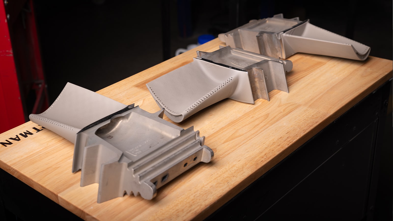
The rotor architecture between the .03 and .04 is closely related, and some structural rotating components carry across the variant boundary. However, the hot gas path hardware — Stage 1, 2, and 3 buckets and nozzles — uses variant-specific cooling geometries and TBC specifications. Installing .03 HGP components in a .04 unit, or vice versa, risks operating outside the thermal design envelope for that specific hardware, with potential consequences for component life and inspection interval validity.
Combustion hardware is not interchangeable between .03 DLN 2.6-equipped units and earlier DLN 2.0+ variants, as noted above. Compressor blades are stage-specific and variant-specific in many rows. Bearings, seals, and casings show more cross-variant compatibility, but this should be verified against GE Vernova engineering documentation or through a qualified repair facility rather than assumed.
The practical implication for spare parts strategy is that a mixed fleet of .02, .03, and .04 units cannot be supported by a single shared HGP inventory without careful part number verification. Third-party repair shops with GE Frame 7FA experience — and the documentation to support variant-specific scoping — are a meaningful resource here. [Gas turbine major inspection services](https://alliedpg.com/gas-turbine-major-inspection-services/) scoped to the correct variant avoid the costly errors that come from treating the 7FA platform as a single undifferentiated fleet.
Can a 7FA.01 or 7FA.02 Be Upgraded to 7FA.04 Performance Standards?
The answer is yes in a qualified sense — and the qualification matters. No upgrade path converts a .01 unit into a .04 unit wholesale, because the structural envelope and some dimensional constraints of the original build remain. What is achievable is a staged set of upgrades that close the performance gap meaningfully.
Upgrade and Retrofit Pathways Available for Earlier 7FA Builds
GE Vernova has offered upgrade kits targeting earlier 7FA builds, including compressor restaging packages, HGP component upgrades to current-generation alloys and TBC systems, and combustion system conversions from DLN 2.0+ to DLN 2.6 where the can geometry permits. Third-party suppliers also offer HGP upgrade packages using equivalent or alternative materials that meet ANSI/ASME B133 gas turbine standards for repair and replacement component qualification.
The economics of upgrading a .01 unit depend heavily on the current condition of the rotor, the remaining service life of the casing and frame, and the site’s operating profile. A unit with a recently refurbished rotor and intact casing geometry may be a strong candidate for an HGP and combustion upgrade. A unit with accumulated casing distortion or rotor repair history that limits future firing temperature is a more complex case.
For operations managers working through this analysis, the most useful starting point is a condition assessment tied to the unit’s actual inspection history — not a generic upgrade economics model. The [GE Frame 7 turbine repair services](https://alliedpg.com/ge-frame-7-turbine-repair-houston/) available through qualified shops include variant-specific condition evaluations that support these decisions with documented findings rather than assumptions.
Why This Matters for Maintenance Planning and Fleet Strategy
The Hot Gas Path (HGP) inspection interval for a GE Frame 7FA unit is typically expressed in equivalent operating hours, with the specific threshold depending on operating mode, fuel type, starts accumulation, and the sub-variant’s design basis. The .04 build, with its improved TBC systems and refined cooling circuits, tends to support longer intervals between HGP inspections under equivalent operating conditions compared to .01 and .02 builds — but only when the correct variant-specific parts were installed at the previous outage.
For maintenance directors managing a fleet across multiple sites, this creates a record-keeping requirement that is easy to underestimate. A unit that received .03 HGP parts during a prior outage (whether due to procurement error or deliberate cross-variant substitution) may be operating on an interval basis that does not reflect the actual installed hardware. The Major Inspection interval calculation, which typically extends to 48,000 equivalent operating hours or beyond on well-maintained F-class units, carries the same dependency on variant accuracy.
Fleet strategy considerations under ISO 3977 procurement evaluation frameworks also reward variant clarity — particularly for operators comparing levelized cost of energy across a mixed fleet or modeling future capital expenditure requirements for major outages.
Conclusion: Getting the Variant Right Before the Work Begins
The 7FA.04 is not a minor revision of earlier builds. The compressor, hot gas path, combustion system, and control architecture all changed in ways that directly affect parts procurement, inspection intervals, and long-term operating costs. Understanding those boundaries — particularly the rotor parity between the .03 and .04 combined with the combustion hardware incompatibility — is the single most important fact for any engineer or maintenance director managing a mixed 7FA fleet.
If you’re heading into an outage and the variant documentation for your unit is incomplete or inconsistent with the parts history, that is worth resolving before the work begins rather than during it.
Allied Power Group works with operators across the full 7FA platform, including component repair, hot gas path overhauls, and parts procurement scoped to the correct sub-variant. If you’re not certain which build standard your unit reflects, or if you’re planning an outage and want a second set of experienced eyes on the scope, the team at Allied Power Group is reachable at (281) 444-3535.
Frequently Asked Questions
What is the difference between the GE 7FA.04 and earlier 7FA models?
The 7FA.04 introduced upgraded compressor aerofoils, revised hot gas path components with enhanced Thermal Barrier Coatings (TBC), an improved DLN 2.6 combustion system, and Mark VIe control upgrades — delivering higher output and improved efficiency compared to 7FA.01 through 7FA.03 builds.
What upgrades did GE introduce with the 7FA.04 variant?
GE Vernova introduced redesigned compressor aerofoils with higher pressure ratio, updated Stage 1 through Stage 3 bucket and nozzle materials with improved cooling circuits and TBC systems, the DLN 2.6 six-premixer combustion system capable of sub-9 ppm NOx, and the Mark VIe distributed control system with enhanced diagnostics and cybersecurity architecture.
Are 7FA.04 hot gas path parts interchangeable with 7FA.03 components?
Hot gas path components — Stage 1, 2, and 3 buckets and nozzles — are not directly interchangeable between .03 and .04 builds due to variant-specific cooling geometries and TBC specifications. Some structural rotating components carry across the variant boundary, but HGP hardware must be verified against variant-specific documentation before procurement or installation.
What combustion system does the GE 7FA.04 use?
The 7FA.04 uses the DLN 2.6 combustion system, which features six premixers per combustor can and is capable of achieving sub-9 ppm NOx on natural gas at base load under ISO conditions. Earlier 7FA.01 and 7FA.02 builds used the DLN 2.0+ system, which was designed for approximately 25 ppm NOx compliance.
Can a 7FA.01 or 7FA.02 be upgraded to 7FA.04 performance standards?
A full variant conversion is not achievable, but staged upgrades can meaningfully close the performance gap. Available pathways include compressor restaging packages, HGP component upgrades to current-generation alloys and TBC systems, and DLN 2.6 combustion conversions where can geometry permits. Upgrade feasibility depends on the unit’s current condition, rotor service history, and operating profile.